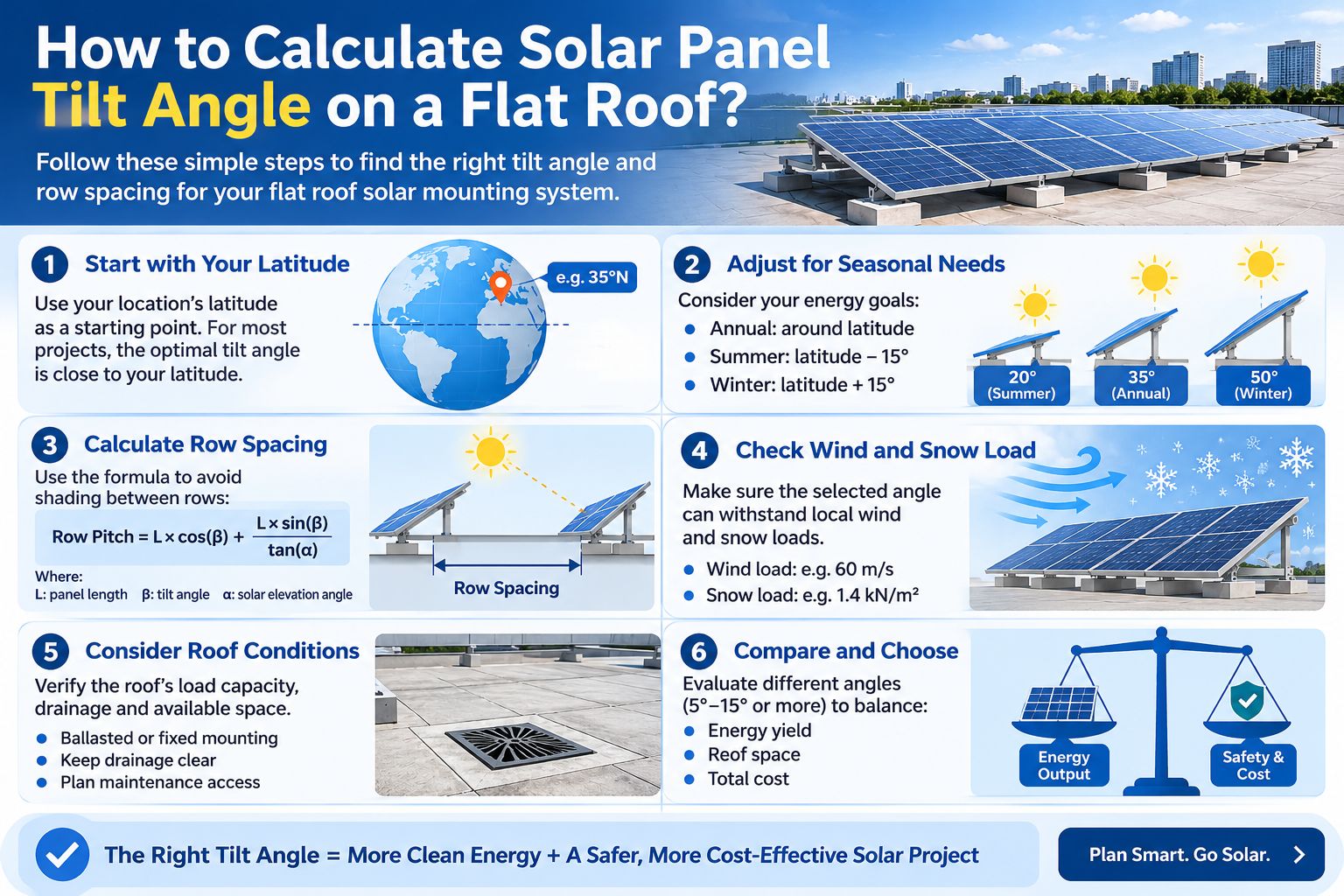
For commercial and industrial rooftop PV projects, the calculation should consider both solar performance and structural limitations. A tilt angle that maximizes annual energy production per panel may not be the most practical choice when roof space, ballast weight, and installation costs are taken into account.
This guide explains how to estimate the solar panel tilt angle, calculate row spacing, and evaluate the mounting requirements for a flat roof solar mounting system.
1. Start with the Geographic Latitude
Geographic latitude provides a useful starting point for estimating the tilt angle of a fixed solar panel system.
As a general rule of thumb, the optimal fixed-panel tilt for maximizing annual energy production is often close to the site's latitude. However, this is an initial estimate, not a universal formula for flat roof installations.
For example:
A project at 20° latitude may start by evaluating a relatively low tilt angle.
A project at 35° latitude may initially evaluate angles around 30°–35°.
A project at 45° latitude may require a higher angle for annual energy optimization, subject to site and structural constraints.
The actual optimum depends on solar radiation data, module orientation, weather patterns, and the project's energy generation objectives.
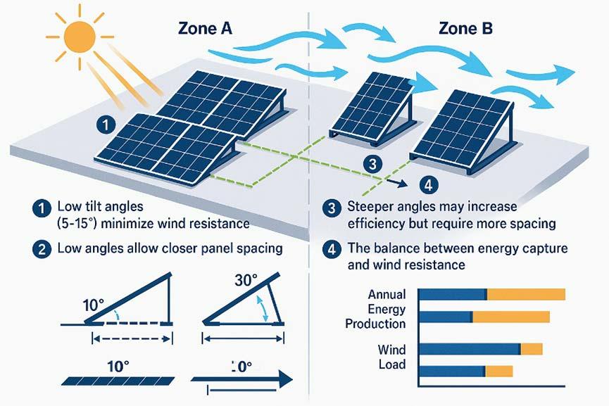
For flat roof solar installations, the latitude-based result should be compared with lower-angle configurations because a steeper mounting angle can increase wind exposure and row spacing requirements.
2. Adjust the Tilt Angle According to Seasonal Energy Requirements
A fixed solar mounting system cannot follow the sun throughout the year. Its tilt angle must therefore be selected according to the project's energy generation priorities.
A commonly used preliminary approach is:
Annual energy optimization: Start by evaluating a tilt close to the site's latitude.
Summer energy optimization: Consider a lower tilt, approximately latitude minus 15°.
Winter energy optimization: Consider a steeper tilt, approximately latitude plus 15°.
These are simplified estimation rules, not final engineering values. Actual energy production should be checked using location-specific solar irradiation data and PV simulation software.
For example, consider a flat roof solar project at 35° north latitude:
| Design Objective | Preliminary Tilt Estimate |
|---|---|
| Annual energy generation | Around 35° |
| Summer-focused generation | Around 20° |
| Winter-focused generation | Around 50° |
These theoretical estimates do not automatically translate into suitable rooftop mounting angles. A 50° tilt, for example, may create significant wind loading and require much greater spacing between panel rows.
For many commercial flat roof projects, engineers also evaluate lower configurations such as 5°–15° to improve roof utilization and reduce structural demands.
3. Calculate the Solar Panel Row Spacing
After selecting a preliminary tilt angle, the next step is to calculate the distance between adjacent rows.
This is particularly important for flat roofs because the panels are installed above a horizontal surface. If the front row casts a shadow onto the next row, the shaded modules may experience reduced power output.
The required spacing depends on:
- Solar panel length along the tilted direction.
- Selected tilt angle.
- Solar elevation angle at the design time.
- Panel orientation and row direction.
- Acceptable shading loss.
The Row Spacing Formula
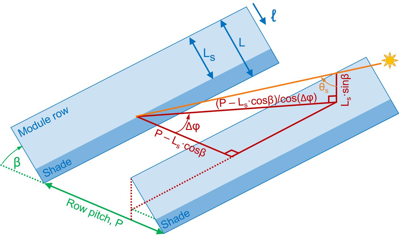
For a simplified layout with rows facing the equator and the sun perpendicular to the panel rows, the row pitch can be estimated using:
Row Pitch = L × cos(β) + [L × sin(β) / tan(α)]
Where:
| Symbol | Meaning |
|---|---|
| Row Pitch | Horizontal distance from one row to the corresponding point on the next row |
| L | Panel dimension along the tilted plane |
| β | Solar panel tilt angle |
| α | Solar elevation angle at the selected design time |
The formula contains two parts:
L × cos(β): Horizontal footprint of the tilted panel.
L × sin(β) / tan(α): Additional horizontal distance required to accommodate the calculated shadow.
The formula calculates the row pitch, not just the clear gap between panels. To obtain the clear spacing, subtract the horizontal footprint of the panel.
Example: Calculate Row Spacing for a Flat Roof Solar System
Assume the project has the following design conditions:
| Parameter | Value |
|---|---|
| Panel length along tilted plane | 2.28 m |
| Panel tilt angle | 10° |
| Project latitude | 35° N |
| Design date | Winter solstice |
| Solar elevation | 31.55° at solar noon |
For a simplified south-facing layout in the Northern Hemisphere, the solar elevation angle at solar noon on the winter solstice can be estimated as:
Solar Elevation = 90° − Latitude − 23.45°
Substituting 35°:
Solar Elevation = 90° − 35° − 23.45° = 31.55°
Now calculate the horizontal panel footprint:
2.28 × cos(10°) = 2.245 m
Calculate the shadow distance:
[2.28 × sin(10°)] / tan(31.55°) ≈ 0.645 m
Therefore:
Row Pitch = 2.245 + 0.645 = 2.89 m
Estimated result:
Row-to-row pitch: approximately 2.89 m
Horizontal panel footprint: approximately 2.245 m
Clear gap between rows: approximately 0.645 m
This is a simplified calculation for avoiding inter-row shading at solar noon on the winter solstice. It does not guarantee zero shading during early morning or late afternoon. A detailed project layout should also consider solar azimuth, row direction, roof obstructions, and the acceptable shading loss.
4. Consider the Effect of Tilt Angle on Wind Load
The tilt angle affects not only solar performance but also the structural forces acting on the mounting system.
As the panel angle increases, the exposed surface and aerodynamic behavior of the array change. This can increase the wind forces that the mounting structure must resist, depending on the building and array configuration.
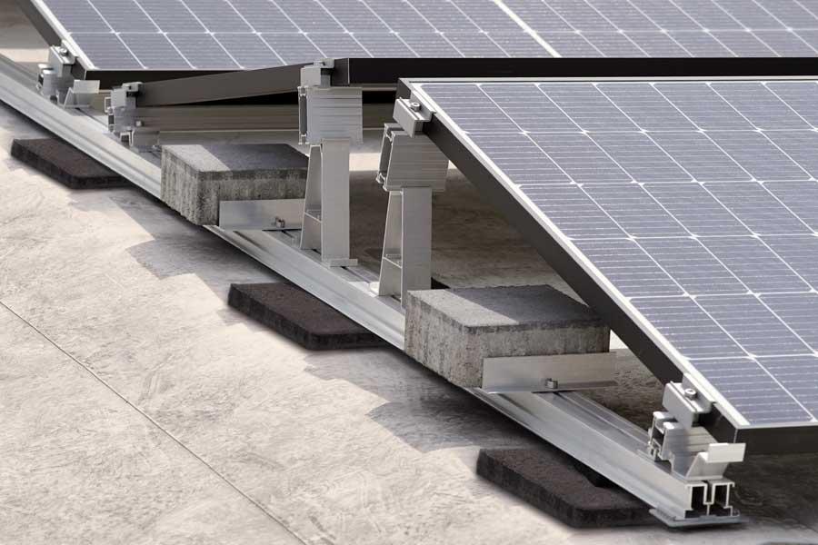
For a ballasted solar mounting system, this issue is particularly important because the system relies on engineered ballast arrangements rather than conventional roof anchors to provide stability.
Before confirming the tilt angle, the structural design should consider:
Local basic wind speed.
Building height and terrain exposure.
Roof edge and corner wind zones.
Panel dimensions and mounting height.
Ballast weight and distribution.
Roof load-bearing capacity.
For example, a low-angle ballasted solar roof mount may be more practical for a commercial building exposed to strong winds than a steeply tilted configuration. However, the final decision must be supported by structural calculations rather than tilt angle alone.
The same principle applies to snow loads. A steeper panel angle may encourage snow movement under certain conditions, but the mounting structure must still be designed for the applicable snow load.
5. Check Roof Load Capacity and Ballast Requirements
A flat roof solar mounting system must be compatible with the structural capacity of the building.
For a ballasted system, the roof supports the combined weight of:
Solar modules.
Aluminum mounting rails and brackets.
Concrete ballast or other ballast components.
Fasteners and associated accessories.
Applicable maintenance and environmental loads.
Increasing the tilt angle may change the wind forces and the amount or distribution of ballast required. Therefore, it is not sufficient to calculate the solar angle and then select ballast weight independently.
The roof's allowable additional load should be checked before finalizing the system design.
If the roof cannot safely support the required ballast, a mechanically fixed mounting solution may need to be evaluated, provided that the roof structure and waterproofing details allow suitable anchoring.
For this reason, the tilt angle, mounting foundation, and ballast arrangement should be developed as part of the same engineering design.
6. Compare Different Tilt Angles Before Finalizing the Design
A single theoretical calculation does not necessarily identify the most cost-effective solution.
For commercial rooftop projects, it is useful to compare several possible angles and evaluate their effects on the complete system.
| Evaluation Factor | Lower Tilt | Higher Tilt |
|---|---|---|
| Solar orientation | May be less favorable in some seasons | May improve seasonal solar exposure |
| Wind exposure | Often easier to manage, subject to design | May increase structural demands |
| Row spacing | Generally requires less space | Generally requires more space |
| Roof utilization | May allow more modules per roof area | May reduce module density |
| Ballast design | Project-specific calculation required | May require different ballast arrangements |
| Mounting structure | May use a lower-profile configuration | May require a taller support structure |
For example, an EPC contractor may compare 5°, 10°, and 15° configurations rather than automatically selecting the latitude-based angle.
The best option is the one that delivers an appropriate balance between annual energy generation, installed capacity, structural safety, and total project cost.
7. Use Solar Design Software to Verify the Calculation
Manual calculations are useful for preliminary planning, but they should not replace a detailed solar energy assessment.
Tools such as NREL's PVWatts can help estimate energy production under different tilt and orientation settings. More detailed PV simulation and structural design tools can be used when a project requires more comprehensive analysis.
A proper design review should verify:
Annual energy production at different tilt angles.
Solar azimuth and elevation throughout the year.
Inter-row shading at relevant design times.
Wind and snow loading.
Roof capacity and ballast requirements.
Available installation and maintenance space.
Using simulation results together with structural calculations gives a more reliable basis for selecting a flat roof solar panel mounting system.
8. Information Needed to Calculate the Tilt Angle for Your Project
If you are requesting a flat roof solar mounting solution from a manufacturer, providing the following information will help the engineering team evaluate the appropriate configuration.
| Required Information | Why It Matters |
|---|---|
| Project location and latitude | Used for preliminary solar angle calculations |
| Solar panel dimensions | Determines panel footprint and shadow height |
| Module orientation | Affects layout and row spacing |
| Target tilt angle or range | Defines the mounting geometry |
| Roof type and construction | Determines foundation options |
| Roof load capacity | Checks whether the roof can support the system |
| Local wind speed | Required for structural design |
| Local snow load | Required where snow conditions apply |
| Available roof area | Determines module quantity and array layout |
| Foundation preference | Helps evaluate ballasted or mechanically fixed solutions |
With these details, the mounting structure can be evaluated according to the actual project conditions instead of relying on a generic tilt-angle recommendation.
Conclusion
Calculating the tilt angle for flat roof solar panels involves several connected steps: estimating the initial angle from geographic location, adjusting it for seasonal energy requirements, calculating row spacing, and checking structural conditions.
The latitude-based method provides a useful starting point, while the row spacing formula helps estimate the distance needed to reduce inter-row shading. However, neither calculation should be used independently of wind load, roof capacity, ballast requirements, and the overall PV layout.
For commercial and industrial projects, the best tilt angle is ultimately the one that provides a practical balance between energy production, roof utilization, structural reliability, and installation cost.
Wuxi Chenglida Machinery supplies flat roof solar mounting structures and ballasted PV mounting solutions for different rooftop project requirements. By reviewing the roof construction, module specifications, project location, and design loads, a suitable mounting configuration can be evaluated for each installation.