A flat roof solar mounting system adds weight to an existing building and changes how loads are transferred through the roof structure. Solar modules, aluminum rails, mounting brackets, concrete ballast, wind uplift, and snow accumulation all need to be considered during system design.
This is particularly important for commercial and industrial buildings, where roof structures may already support HVAC equipment, ventilation systems, pipelines, and other permanent installations.
Understanding how roof load affects solar mounting design helps project developers choose the right foundation method, mounting structure, and panel layout before installation begins.
1. What Types of Loads Must a Flat Roof Support?
A rooftop solar installation introduces several types of loads. They should be evaluated together rather than treated as separate issues.
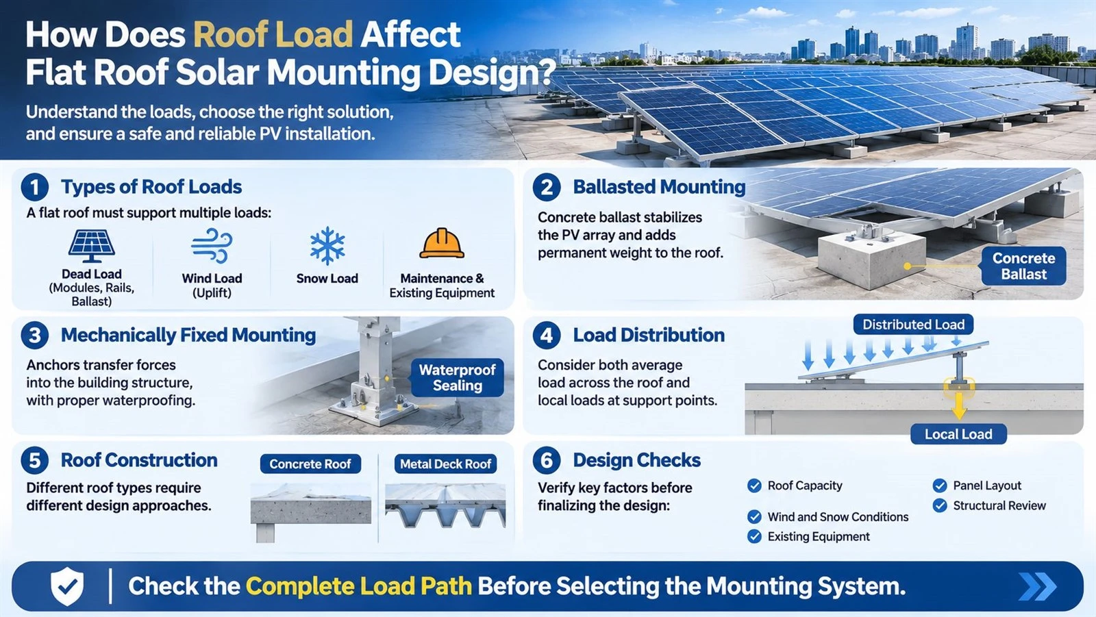
Dead Load
Dead load refers to the permanent weight of the installed solar system. It generally includes:
- Solar panels and their frames.
- Aluminum mounting rails and brackets.
- Clamps, connectors, and fasteners.
- Concrete ballast blocks, where applicable.
- Other permanently installed accessories.
For a ballasted solar mounting system, ballast can represent a significant part of the additional dead load. Its weight must be included in the roof's structural assessment.
Wind Load
Wind creates pressure and uplift forces on solar panels and their supporting structures. On flat roofs, wind conditions can vary across different roof zones.
Roof edges and corners may experience different wind effects from the central roof area. Building height, surrounding terrain, parapets, panel tilt angle, and array configuration also influence the design.
The mounting system must transfer these forces safely through its ballast arrangement or mechanical connections.
Snow Load
In regions with significant snowfall, accumulated snow adds vertical load to the roof and solar array.
The design should account for the applicable local snow load, including relevant distribution and accumulation conditions. Panel tilt angle alone cannot determine whether a system is safe under snow loading.
Maintenance and Other Existing Loads
Roof maintenance activities, access routes, and existing equipment also matter.
An installation should not be designed using the roof's total nominal capacity without accounting for loads already present. The available capacity for additional solar equipment may be substantially lower than the building's original design capacity.
2. Why Roof Load Capacity Determines the Mounting Method
The roof's available load capacity is one of the main factors in choosing between a ballasted and a mechanically fixed solar mounting system.
These two approaches transfer loads to the building in different ways.
Ballasted Solar Mounting System
A ballasted solar mounting system uses concrete blocks or other engineered ballast components to stabilize the photovoltaic array.
Because the system can reduce or avoid conventional roof penetrations, it is often considered for concrete flat roofs where preserving the waterproofing layer is important.
However, the ballast adds permanent weight to the roof. The structural design must verify that the roof can support the combined weight of the panels, mounting structure, and ballast, together with applicable environmental loads.
A ballasted solution may be suitable when:
- The roof has sufficient additional load capacity.
- The project prefers to minimize roof penetrations.
- The roof surface provides suitable support conditions.
- The required ballast arrangement can meet the structural design requirements.
The amount of ballast should be determined through project-specific engineering calculations. It should not be selected using a fixed weight per panel without considering wind conditions and roof structure.
Mechanically Fixed Solar Mounting System
A mechanically fixed mounting system transfers forces through anchors or other designed connections into the building's supporting structure.
This approach may be considered when the roof has limited capacity for additional ballast but provides suitable structural fixing locations.
Its design must address:
- Anchor capacity and connection details.
- Roof deck and supporting member strength.
- Local wind uplift forces.
- Waterproofing and penetration sealing.
- Load transfer from the mounting structure into the building.
A mechanically fixed system does not eliminate structural requirements. It changes how the forces are transferred. The roof deck, beams, and connections must all be suitable for the proposed anchoring arrangement.
Ballasted vs. Mechanically Fixed: What Is the Difference?
| Design Consideration | Ballasted System | Mechanically Fixed System |
|---|---|---|
| Load transfer | Through ballast and roof contact points | Through designed mechanical connections |
| Additional dead load | Includes ballast weight | Generally avoids large ballast loads |
| Roof penetration | Can minimize or avoid conventional penetration | Usually requires designed fixing points |
| Main structural concern | Roof capacity and ballast distribution | Anchor capacity and supporting structure |
| Waterproofing | Requires suitable protection beneath support points | Requires properly designed penetration sealing |
| Typical selection factor | Sufficient roof capacity and penetration restrictions | Suitable structural fixing locations and limited ballast capacity |
Neither method is automatically better. The appropriate choice depends on the roof construction, structural capacity, waterproofing requirements, and project design conditions.
3. Why Total Roof Load Is Not the Same as Load per Square Meter
One common mistake in rooftop solar projects is to divide the total weight of the solar installation by the entire roof area and use the result as the only structural check.
For example, a solar array may have an average additional load of 25 kg/m² across its designated installation area. That figure does not necessarily mean every part of the roof experiences 25 kg/m².
The actual load distribution depends on the mounting structure.
A ballasted system may transfer loads through relatively small support or ballast contact areas. A mechanically fixed system transfers forces through specific anchor points. Both arrangements can create local forces that differ from the average load across the array.
Engineers therefore need to evaluate two related but different questions:
Overall roof loading: Can the roof structure support the additional weight and environmental loads from the complete installation?
Local load transfer: Can the roof deck, supporting beams, contact points, and connections safely carry the forces applied at their specific locations?
This distinction is important when evaluating older buildings, lightweight roof decks, and roofs with long structural spans.
A mounting system may appear acceptable based on average load calculations but still require changes to its support spacing or connection arrangement after a local structural assessment.
4. How Does Roof Structure Affect Solar Mounting Design?
Not all flat roofs are constructed in the same way. The roof material and supporting structure influence which mounting solutions are practical.
Concrete Flat Roofs
Concrete roofs are commonly evaluated for ballasted solar mounting systems because they can provide a stable supporting surface.
However, concrete construction does not automatically mean unlimited load capacity. The slab thickness, reinforcement, structural span, supporting beams, building condition, and existing loads must still be reviewed.
For a concrete flat roof, the mounting design should consider ballast placement, support contact areas, waterproofing protection, drainage, and maintenance access.
Metal Deck Roofs
Metal deck roofs are often lighter than concrete roof structures. Their load capacity can depend heavily on deck thickness, profile, span, purlin spacing, and the supporting steel frame.
A ballasted system may be unsuitable if the additional dead load exceeds the available capacity. Mechanically fixed mounting may be evaluated where suitable connections to the supporting structure can be designed.
Fixing directly to a metal roof sheet without verifying the complete load path is not an adequate structural design approach.
Existing or Older Roofs
For existing buildings, the original structural drawings may not reflect current conditions.
Previous renovations, added equipment, corrosion, water damage, and changes to building use can affect the available capacity.
A structural assessment should therefore verify the actual condition of the roof before the solar mounting system is finalized.
5. How Wind and Snow Loads Change the Mounting Structure
Roof load assessment is not limited to the weight of the solar equipment. Environmental loads can determine the required structure, connections, and foundation arrangement.
Wind Load and Uplift Resistance
Wind can create uplift forces that attempt to lift the solar modules and mounting structure away from the roof.
The mounting system must provide a reliable load path from the modules through the clamps, rails, brackets, and foundation or anchors into the building structure.
For a ballasted solar roof mount, the ballast arrangement must provide sufficient resistance under the applicable design wind conditions. The calculation should consider building height, roof zones, panel tilt, array geometry, and local wind requirements.
A higher tilt angle may change the aerodynamic forces acting on the array. Therefore, increasing the tilt angle without reviewing the structural design can lead to an unsuitable mounting configuration.
Snow Load and Structural Support
Snow load adds vertical demand to the roof and supporting structure.
The mounting design should consider the local design snow load and how the solar array affects snow distribution. In some situations, panel rows, parapets, or nearby equipment can contribute to uneven accumulation.
For example, a project with a specified snow load of 1.4 kN/m² needs to be checked against that design requirement. This value should not be assumed suitable for projects in other locations.
The final design must satisfy the applicable local structural requirements for both the roof and the solar mounting system.
6. How Roof Load Affects Panel Layout and Tilt Angle
Roof capacity can also influence how many solar panels can be installed and how they are arranged.
A steeper tilt angle may increase wind exposure and change the structural forces acting on the mounting system. It can also increase the distance needed between rows to reduce shading.
A lower tilt angle may allow a more compact layout, but the resulting energy yield and drainage conditions still need to be evaluated.
When roof load is a limiting factor, designers may compare different configurations based on:
- Panel tilt angle.
- Landscape or portrait module orientation.
- Rail and support spacing.
- Ballast quantity and distribution.
- Total installed module capacity.
- Maintenance and drainage clearance.
The objective is not simply to install the maximum number of panels. It is to achieve a practical PV layout that meets the building's structural limits and project energy requirements.
7. How to Evaluate Roof Load Before Ordering a Solar Mounting System
Before requesting a quotation, project developers and EPC contractors should collect the information needed for a preliminary technical evaluation.
| Information | Why It Is Important |
|---|---|
| Roof construction | Identifies the type of supporting structure |
| Structural drawings | Shows slab, deck, beam, and support details |
| Allowable additional load | Helps determine available capacity for solar equipment |
| Existing rooftop equipment | Accounts for loads already acting on the roof |
| Project location | Establishes the relevant environmental design conditions |
| Design wind speed | Used to evaluate wind pressure and uplift |
| Design snow load | Determines applicable snow-related structural requirements |
| Solar module specifications | Provides panel dimensions and weight |
| Preferred foundation method | Helps evaluate ballasted or mechanically fixed mounting |
| Roof layout | Identifies obstructions, drainage outlets, and available installation areas |
If the allowable additional roof load is unknown, it should be verified by a qualified structural engineer. A mounting supplier can provide system information and design inputs, but should not assume that the roof is suitable without structural evidence.
8. What Should Be Changed If the Roof Has Limited Load Capacity?
If the initial assessment shows that the roof cannot support the proposed solar installation, the project may need to be redesigned.
Possible measures include:
Evaluate a mechanically fixed solution: Where the roof structure allows suitable anchoring, a mechanically fixed system may reduce the need for heavy concrete ballast.
Review the panel layout: Adjusting module orientation, support spacing, and array configuration may help optimize the installation within the available roof area.
Compare lower-profile configurations: A different tilt angle or mounting geometry may reduce certain structural demands, subject to engineering verification.
Check alternative installation areas: If the existing roof cannot support the required system, another roof section, ground-mounted PV installation, or solar carport may be considered.
These changes should be evaluated by the project engineering team. Reducing ballast or changing support spacing without checking wind resistance and load transfer can create new structural risks.
Conclusion: Roof Load Should Be Checked Before Selecting the Solar Mounting System
Roof load affects almost every major decision in flat roof solar mounting design, from the foundation method and ballast arrangement to panel tilt angle, support spacing, and array layout.
A ballasted solar mounting system may be appropriate for a concrete flat roof with sufficient load capacity, while a mechanically fixed solution may be more suitable where additional ballast is restricted and suitable structural connections are available.
The key is to evaluate the complete load path, not just the average weight of the solar panels. Dead load, wind uplift, snow load, existing rooftop equipment, and local support conditions must all be considered before installation.
Wuxi Chenglida Machinery supplies flat roof solar mounting structures and ballasted PV mounting solutions for commercial and industrial projects. Roof construction, available load capacity, module specifications, and local design conditions can be used as the basis for evaluating a suitable mounting configuration.