For a flat roof PV mounting system, the calculation is not simply a matter of converting wind speed into wind pressure. The building height, roof dimensions, roof-edge zones, panel tilt angle, array layout, and mounting method all influence the design load.
This guide explains how engineers approach wind load calculations for flat roof solar mounting systems, what information is required, and how the calculated loads affect mounting structure selection.
1. Understand the Main Types of Wind Loads on Flat Roof Solar Panels
Before calculating wind load, it is important to distinguish between the forces acting on a rooftop solar array.
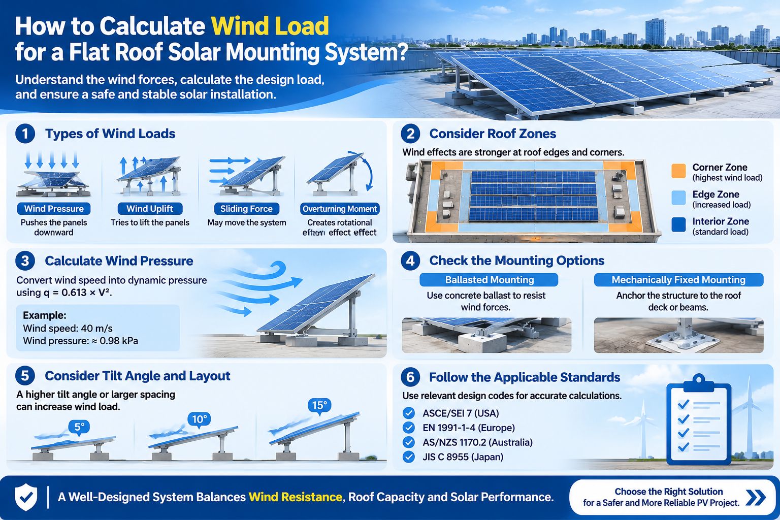
Wind pressure is the pressure exerted by moving air on a surface. Depending on wind direction and the surface orientation, it can act downward or horizontally.
Wind uplift is the upward force created when airflow produces lower pressure above or around the solar panels. It can pull panels, clamps, rails, and mounting bases away from the roof.
Sliding force is the horizontal force that may cause a mounting assembly to move across the roof surface, particularly in a ballasted solar mounting system.
Overturning moment occurs when wind forces create a rotational effect around the mounting base. This can cause one side of the structure to lift or lose contact with the roof.
These forces do not act independently in every design. A mounting system must be checked against the relevant load combinations and failure modes, including uplift, sliding, overturning, and the strength of its individual connections.
2. Collect the Project Data Before Calculating Wind Load
A reliable wind load calculation starts with project-specific information. Using only the local wind speed is not sufficient.
| Required Information | Why It Matters |
|---|---|
| Project location | Determines the applicable wind design requirements and basic wind speed |
| Basic wind speed | Provides the starting point for calculating wind pressure |
| Building height | Affects wind exposure and velocity pressure |
| Terrain and exposure category | Describes how surrounding buildings, trees, and open areas affect airflow |
| Building dimensions | Helps determine roof geometry and wind zones |
| Roof edge and parapet height | Influences local airflow and pressure distribution |
| Solar panel dimensions | Determines the exposed area used in force calculations |
| Panel tilt angle | Changes the aerodynamic behavior of the array |
| Array layout and edge distance | Affects wind exposure and pressure coefficients |
| Mounting method | Determines how wind forces are transferred to the roof |
For example, a solar array installed near the center of a large commercial roof may experience different wind pressures from an array installed close to a roof corner. The same mounting system may therefore require different attachment spacing or ballast arrangements depending on its position.
3. Calculate the Basic Wind Pressure
The first step is to convert the design wind speed into a reference velocity pressure.
For a simplified preliminary estimate, the dynamic pressure of moving air can be expressed as:
q = 0.5 × ρ × V²
Where:
q = dynamic pressure (Pa)
ρ = air density (kg/m³)
V = wind speed (m/s)
Using a standard air density of approximately 1.225 kg/m³, the formula becomes:
q ≈ 0.613 × V²
This equation shows why wind pressure increases rapidly as wind speed rises. Pressure is proportional to the square of wind speed, rather than increasing at the same rate.
Example: Convert Wind Speed into Dynamic Pressure
Assume the reference wind speed is 40 m/s.
q = 0.613 × 40²
q = 0.613 × 1,600
q = 980.8 Pa ≈ 0.98 kPa
For comparison:
| Wind Speed | Approximate Dynamic Pressure |
|---|---|
| 30 m/s | 0.55 kPa |
| 40 m/s | 0.98 kPa |
| 50 m/s | 1.53 kPa |
| 60 m/s | 2.21 kPa |
These values are simplified dynamic pressures, not final design pressures for a solar mounting system. They do not include the full set of adjustments and pressure coefficients required by a building wind-load standard.
For structural design, engineers must use the wind speed definition, exposure factors, height adjustments, directionality factors, and other parameters specified by the applicable local standard.
4. Determine the Wind Pressure Coefficients for the Roof and Solar Array
After calculating the reference velocity pressure, the next step is to determine how wind acts on the actual rooftop configuration.
Wind pressure is not uniform across a flat roof. Roof corners and perimeter areas can experience higher suction than the central roof area because airflow separates and accelerates around building edges.
A typical roof assessment distinguishes between:
Corner zones: Often subject to particularly high local wind effects.
Edge zones: Exposed to stronger wind suction than many interior areas.
Interior zones: Generally experience a different pressure distribution from roof perimeter areas.
The exact zone dimensions and pressure coefficients must be determined using the applicable design standard. They should not be selected using a universal percentage or fixed distance.
The solar array itself also affects the calculation. Panel tilt, clearance above the roof, gaps between modules, row spacing, array dimensions, and distance from the roof edge can all change the wind forces acting on the system.
For this reason, engineers should assess the actual PV array layout rather than treating the entire roof as one uniform wind-pressure area.
5. Calculate Wind Uplift on the Solar Panels
Once the applicable design wind pressure has been established, the wind force acting on a panel or a defined part of the array can be estimated using:
F = p × A
Where:
F = wind force (N)
p = applicable net design wind pressure (Pa)
A = effective loaded area (m²)
For example, if a calculated net uplift pressure of 1.0 kPa acts on an effective panel area of 2 m²:
F = 1.0 × 2 = 2.0 kN
This means the estimated upward force on that loaded area is 2.0 kN.
However, this is only a simplified force calculation. The pressure used must already account for the relevant aerodynamic and code-based factors. The effective loaded area must also reflect the actual load distribution and the design method being used.
For a complete flat roof solar mounting system, engineers need to evaluate how the uplift force is transferred through the module clamps, mounting rails, support brackets, base connections, and ultimately into the roof structure.
A connection that appears adequate when checked individually may not be sufficient if the complete load path is not considered.
6. Check the Wind Load on Ballasted and Mechanically Fixed Mounting Systems
The mounting method changes how wind forces are resisted. This is particularly important when comparing a ballasted solar mounting system with a mechanically fixed system.
Ballasted Solar Mounting System
A ballasted solar mounting system uses additional weight to resist wind-induced uplift and movement, rather than relying entirely on mechanical roof penetrations.
The required ballast is not determined by simply dividing the total uplift force by gravitational acceleration. The design must also consider:
Sliding resistance between the mounting base and roof surface.
Overturning stability under wind pressure.
Load distribution across the ballast supports.
Friction characteristics of the roof protection or separation layer.
Local roof load capacity and allowable concentrated loads.
The effects of different wind zones across the array.
The final ballast arrangement may vary between corner, edge, and interior positions. Applying the same ballast quantity to every support point without checking the local wind conditions can lead to an inefficient or unsafe design.
Mechanically Fixed Solar Mounting System
A mechanically fixed system transfers wind forces through anchors or other structural connections into the roof deck or supporting structure.
The design should verify the strength of the mounting base, fasteners, anchors, rails, clamps, and the supporting roof structure. Pull-out resistance, connection capacity, and the condition of the existing roof construction are particularly important.
Mechanical fixing can reduce the need for additional ballast, but it introduces connection and waterproofing considerations. The selected fixing method must be compatible with the actual roof construction.
7. How Panel Tilt Angle and Array Layout Affect Wind Load
Panel tilt angle is an important design variable for a flat roof solar mounting system.
A higher tilt angle changes the surface exposed to the wind and can increase aerodynamic forces and overturning effects. A lower profile may reduce wind exposure, but the final result also depends on panel spacing, array configuration, roof-edge conditions, and the applicable pressure coefficients.
Array layout matters as much as the individual panel angle.
For example, panels positioned close to the roof perimeter may be subject to different wind pressures from panels in the central area. The distance between rows, gaps between modules, and the height of the panel above the roof can also influence pressure equalization and wind exposure.
This is why a flat roof solar mounting design should be evaluated as a complete array rather than as a single isolated panel.
8. Which Wind Load Standards Should Be Used?
The applicable wind-load standard depends on the project location and local approval requirements. Commonly referenced standards include:
| Standard | Main Application |
|---|---|
| ASCE/SEI 7 | Minimum design loads for buildings and other structures in the United States |
| EN 1991-1-4 | Wind actions for structural design under the Eurocode framework |
| AS/NZS 1170.2 | Structural design actions – wind actions in Australia and New Zealand |
| JIS C 8955 | Design guide for structures supporting photovoltaic arrays in Japan |
These standards do not necessarily use identical wind-speed definitions, calculation procedures, or pressure coefficients. A wind speed specified under one standard should not be directly substituted into another standard without checking its definition and required adjustments.
For rooftop PV arrays, the design method must also address the aerodynamic behavior of the solar panels and mounting arrangement. Where standard provisions do not adequately cover a particular configuration, project-specific engineering analysis or wind tunnel testing may be necessary.
9. What Should Solar Mounting Suppliers Check Before Confirming a Design?
When a buyer requests a flat roof solar mounting system for a specific wind condition, the supplier needs more than a single wind-speed figure to assess the structure.
The following information helps avoid repeated design changes:
- Project location and applicable wind-load standard.
- Building height, roof dimensions, and roof construction.
- Roof edge, corner, and parapet conditions.
- Solar panel dimensions, weight, and installation orientation.
- Required panel tilt angle and mounting clearance.
- Total array layout and distance from roof edges.
- Whether the project uses a ballasted or mechanically fixed mounting system.
- Required design loads and any local approval or testing requirements.
With these details, the mounting supplier and structural engineer can assess the required support spacing, rail configuration, connection capacity, and ballast arrangement.
For commercial rooftop projects, it is also important to check whether the existing roof can accommodate the additional dead load and concentrated support reactions. A wind-resistant mounting system must still be compatible with the load capacity of the building.
Conclusion
Calculating wind load for a flat roof solar mounting system involves more than converting wind speed into pressure. The complete assessment must consider roof wind zones, building height, terrain exposure, panel tilt, array layout, wind uplift, and the way forces are transferred through the mounting structure.
For a ballasted system, the calculation determines whether the ballast arrangement can resist uplift, sliding, and overturning without exceeding the roof's load capacity. For a mechanically fixed system, it helps establish the required capacity of anchors, fasteners, rails, and supporting roof members.
A reliable design starts with accurate project information and follows the wind-load standard applicable to the installation location. This is essential for selecting a suitable flat roof solar mounting system and avoiding both under-designed connections and unnecessary structural weight.